This website shows the development of a circuit switching a kitchen extraction/range hood automatically on demand
DISCLAIMER: This is a hobbyist project that is not meant to be a finished end customer product.If you choose to replicate this build, you are doing so at your own risk!!
About
In our small family we like to cook often, which is very nice. However, especially when sautéing ingredients, there is quite a bit of fumes and food odor. The great invention the hood is supposed to save the apartment from smelling uniformly like "appetizer".
But that's where the practice strikes: such a device helps only when you turn it on. And this often doesn't happen when several family members also use the kitchen as a convivial place, distracting the conversation from secondary matters, such as turning on the hood.
Today there should be better ways to do this, right? Maybe even without modifying the hood or the stove itself.
Functional description
Since a stove needs relatively large currents for its operation, it is very easy to see whether the stove is in operation by means of a current transformer. This works both for classic appliances with heating coils in cast iron or under glass ceramic, but also for induction cooktops.
Quadruple cooktops occupy, at least one Germany, two phases of 3 phase AC line. The third phase of the stove wall box is mostly intended for the oven. Therefore, if one forms the (vector) sum of the currents of the two stove phases, one can reliably deduce whether cooking is in progress.
This summation results directly from the physics of magnetic current transformers, which are nothing more than a transformer with one primary winding and many secondary windings. The magnetic fluxes of the conductors passing through the transformer add up and produce a current signal proportional to their sum.
Today, asian current transformers can be purchased at a very reasonable price, so that this seems to be a viable way to automation.
Current transformers convert the current AC line of the stove and are galvanically separated, so processing of their output can be done rather safely with simple microcontroller circuits.
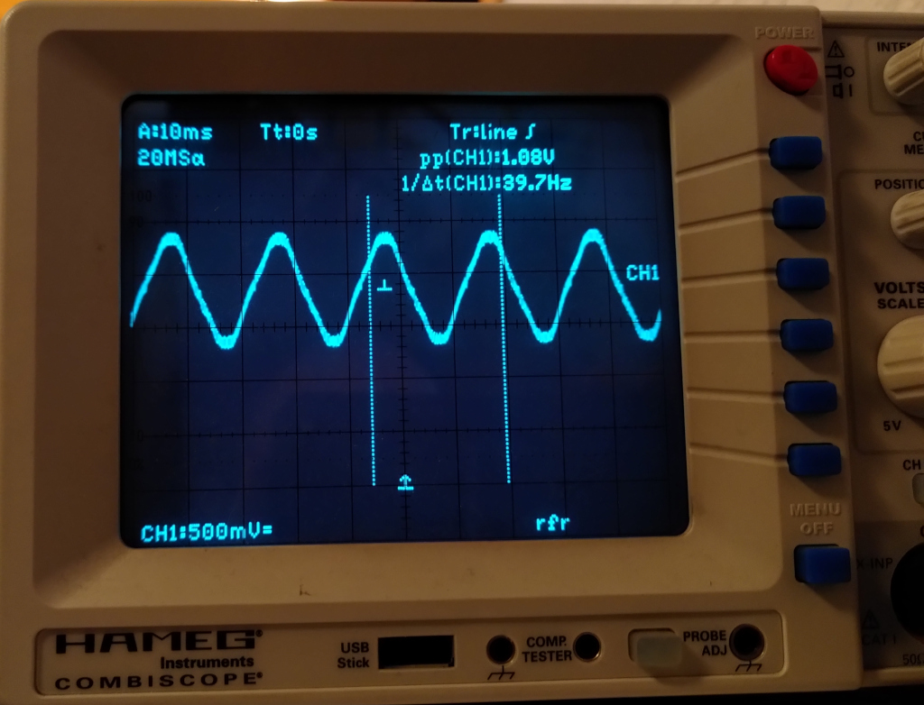
The code running on the arduino does most of its heavy lifting using EmonLibrary, a library intended for energey monitoring. It can filter out the DC-Offset we added using the voltage divider and calculates a RMS value. All of this could be done from scratch but one can be lazy these days.
Schematic diagram

Da der Stromwandler, wie der Name schon andeutet, ein Stromsignal in eines mit einer anderen Skalierung umwandelt, muss dieses zur Auswertung erst einmal in ein Spannungssignal verwandelt werden. Dies geschieht mit einem einfachen Widerstand parallel zum Wandlerausgang.
Since the current transformer, as the name suggests, converts a current signal into one with a different scaling, it must first be converted into a voltage signal for digitization. This is done with a simple resistor in parallel to the converter output.
But watch out: some converters already contain the shunt resistor, like the model SCT-013-005 procured by the author. Then the input of the circuit must be high impedance, therefore R1 has 10kOhm in this schematic!

But why the whole thing with the resistors around the input?
The anlog/digital converters of the ATMega can, just like almost all
other A/D converters in microcontrollers, only measure voltages between
zero volts and the given (positive) reference voltage.
However, the signal of the current converter is a pure AC voltage, so it has just as equal voltage swing in positive as in negative direction. To be able to measure it well, it is therefore advantageously pulled "up" by exactly half of the reference voltage. This is done by R2/R3.

This reference voltage can be generated using the quite stable voltage reference TL431 or simply the plain +5V operating voltage can be used. The latter is not particularly immune to temperature changes, but should actually suffice. Another advantage of the reference TL431 is that the value range of 0..1024 of the 10-bit A/D converter is better used, since the reference voltage, i.e. the one at which 1024 count are reached, is 2.5V and not 5V.
Thus the A/D converted signal from the current transformer maps to larger values. Because one A/D increment corresponds at 5V/1024 to about 4.9mV and at 2.5V it is only 2.4mV, so a signal of maximum one volt (according to the data sheet of the converter) at 5V reference voltage is read as 204 count, at 2.5V it is already 409 count.

The output voltage should be switched off at all poles, i.e. both the neutral and the phase should be interrupted, in case one of the relays sticks. Therefore two separate relays were used which are switched simultaneously.
During commissioning, there was still a small issue: the stove
connection line did not pass by close enough to the exhaust hood, so the
converter could not be placed directly in the kitchen. At least not
without bringing in the big tools and causing a lot of debris.
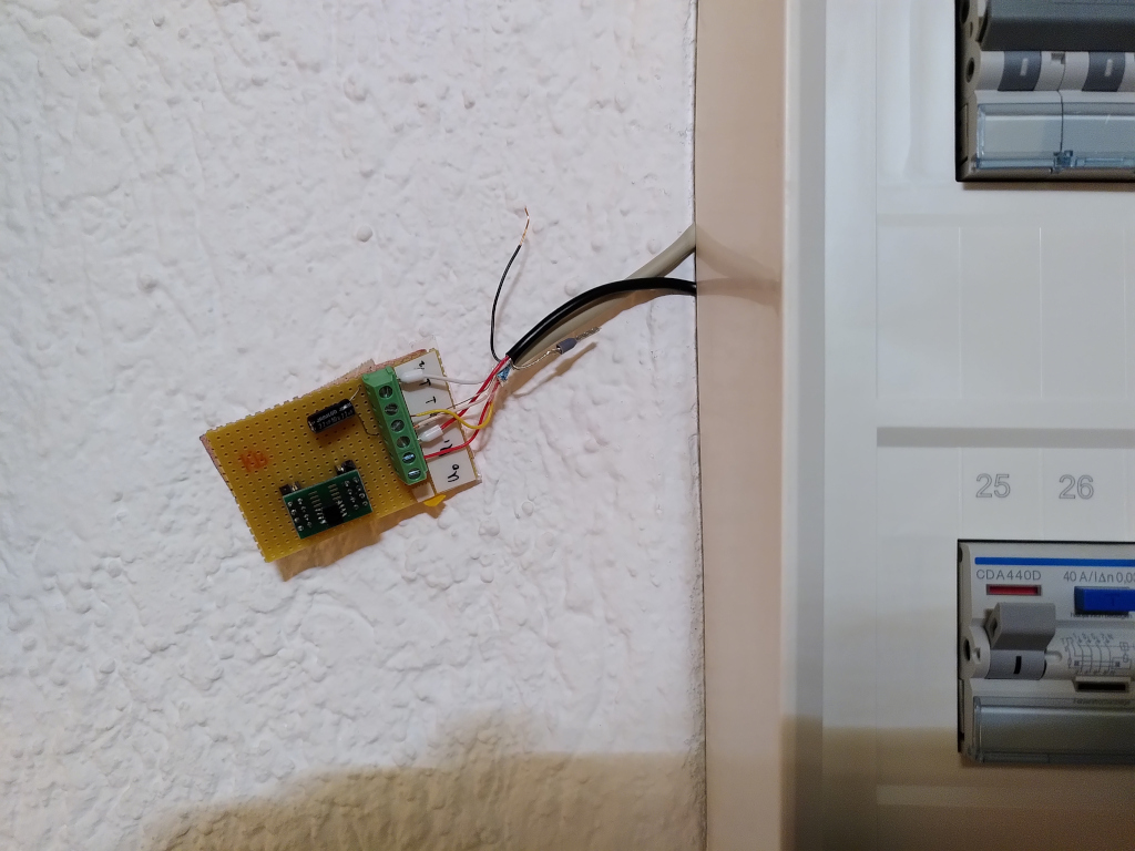
Therefore, this was placed in the sub-distribution box. This is about
20m worth cable away from the range hood, so the signal came back there
via phone line. So far so good, but this line had so much capacitive
loading that the signal was simply unusable. Now a "booster" module
was quickly built, which is simply an opamp as an impedance converter,
so the relatively high impedance output of the converter was converted
to a voltage output, and the signal survives the route largely
unscathed.
Probably this would not have happened with a current transformer with
current output (e.g. the SCT-013-000) with a properly dimensioned load
resistor. Because a current loop should not be so vulnerable.

This board now hangs off the sub-distribution for now.
Mechanical installation
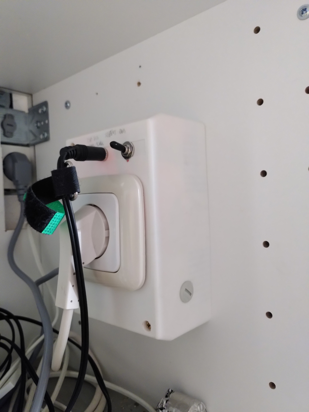
A small case is used as housing, as it was originally meant as a box for four circuit breakers. The electronics built on a breadboard, because the project had to be finished quickly. Here the part with mains voltage and the low voltage part were separated as far as possible.
Components used
- 1x Arduino Nano
- 1x YHDC SCT-013-005 current transformer with integrated ballast 1V/30A output
- 1x 3.5mm Jack
- 1x 3.5mm Plug
- 2x Relay FUJITSU-TAKAMISAWA JS 05-N-K
- 1x Diod 1N4184
- 1x Transistor BC847A
- 1x PCB mouted AC/DC Power Supply 230V to 5V@1A
- 2x Fuse holders
- 2x Screw terminal 3 poles
And some other stuff that here. Like an old wall socket, a power cord with ground line, the chassis, and so on.
Code for the micro controller
As the project is largely using EmonLibrary, so the code itself is rather rudimentary. Here you can find the arduino sketch.