In the following a photovoltaic based DC power supply for various small small consumers in the house.
Among other things, this system also supplies the PiRack.
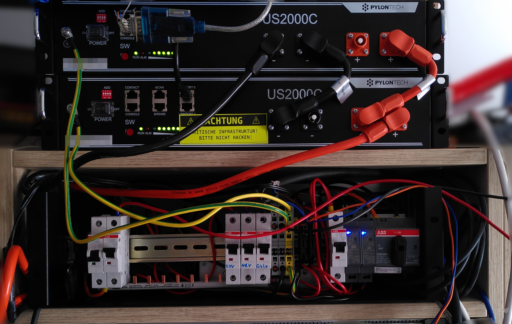
System in operation
General
Energy prices are reaching new record highs every year and things are not getting any better. Therefore in the context of this project I’ll to try to convert as many small consumers as possible to a low voltage low-voltage DC system.
But why?
Trying to connect a PV system to the German power grid, german bureaucracy makes you feel as if you where applying for a permit for a coal power plant than transitioning to more renewable energy supply.
In addition, the feed-in to the public grid is usually not economically viable, since there is a factor of 10 between one’s own purchase price and the feed-in tariff. You only get paid one tenth of the purchase price per kWh.
Therefore, the primary goal must be the highest possible self-consumption. This is the only way to eventually cover the costs of such an installation.
From the point of view of security of supply, a grid-connected system is not always optimal. Should there be a large-scale power failure, most PV systems today cannot be operated in backup mode, or the setup gets much more complicated. In backup/UPS mode, electricity is generated by the PV system or the DC batteries is stepped up to 230V mains voltage and almost all domestic consumers can be operated.
The fire protection regulations of the place of residence can also cause problems, as municipal building codes sometimes prohibit PV systems in densely populated areas as high DC voltages beyond 200V could pose a danger to fire fighters.
Approach
In this project, a low-voltage PV system was constructed to be used for the stand-alone or UPS operation of small loads such as lighting, IT hardware (routers, access points, various Rasperry PIs, laptops).
The aim was also to keep the voltages in the entire PV system in a range that was not dangerous for the fire department.
Lithium-iron phosphate batteries are used as energy storage, currently these represent a good compromise between service life, power density and operational safety.
The distribution implemented on a voltage level of 48V, which is acceptable both in electrical safety as well as the distribution power dissipation.
Thus, 48VDC Power over Ethernet (PoE) is used to power the access points, switches and lighting in some cases.
Laptops are powered with adapters suitable for automotive using locally 12V derived from the battery 48V.
Implementation

Generators
There are two PV panels on the roof, each with 40V open-circuit voltage, 33V nominal voltage at 320Wp. These are connected in series.
This means that the maximum string voltage is approx. 80V. In case of a fire, which hopefully will never occur, this should not pose a significant danger to the the fire brigade.
Distribution
The DC distribution is located in the study, it contains, in addition to the the PV charge controller, four DC/DC converters.
Between the input terminals for the PV panels and the charge controller is an all-pole disconnect switch disconnect the charge controller from the PV panels and stop current flow.
The charge controller operates directly on an unstabilized 48V circuit feeding into the two LiFePo4 accumulators. On this circuit during operation between 47V and 53V can occur.
This voltage is regulated to a constant 48V by means of a DC/DC-converter to supply PoE devices (access points, switches, etc).
24V is also derived from the battery voltage, this is used to power the PiRack, router and home automation gateway. The latter have DC/DC converters to 12V and 5V respectively. This double conversion is not efficient and could, if suitable elements become available again, be replaced by direct 48V/5V or 48V/12V converters.
The 48V and battery voltage are connected via a 4x1.5mm2 cable to the PoE injector on the storage and to the DC sub-distribution in the bedroom.
Of course all circuits are protected by DC approved circuit breakers.
The grounding is only done on the target voltages, the battery and PV voltages and PV voltages are deliberately left floating, also to minimize the risk of to minimize the risk of electric shock.
Recharging
By means of a galvanically isolating laboratory switch-mode power supply, can be recharged with limited power in case of overcast weather. It should be noted that such power supply units will go into a fault condition if the set voltage (in this case (here approx. 50% discharge voltage, 48.2V) and the applied voltage, e.g. the charge voltage of approx. 52V deviate more than a few volts.
Therefore a Schottkey diode was installed to prevent a reverse voltage to the power supply.
The power supply can be switched off at constant predicted sunshine, because it has a certain amount of self-consumption.
Energy storage
Two 19" built-in storage units with a total capacity of 4.8kWh supported the system in case of darkness or power failure for approx. 2.5 days. The aim was to achieve the greatest possible self-sufficiency.
If necessary, one could also upgrade in the storage department.
Bedroom
In the bedroom there are various small consumers, e.g.
- Two reading lamps (IKEA JANSJÖ)
- Two laptops
- 4x USB charging sockets for cell phones and tablets.
For this purpose, the battery voltage is reduced to 12V by means of a DC/DC converter and distributed. Two small DC/DC converters produce the 4.8V for the LED spots.
The USB charging sockets are from the automotive sector and can also be supplied via 12V.
There is a car power supply from Lenovo that provides USB-C PD with 65W, the laptops can be charged using this.
Conclusion
Within the first two months of operation, about 115 kWh were produced and consumed. The power supply only had to run for two weeks, but was not permanently fully loaded.