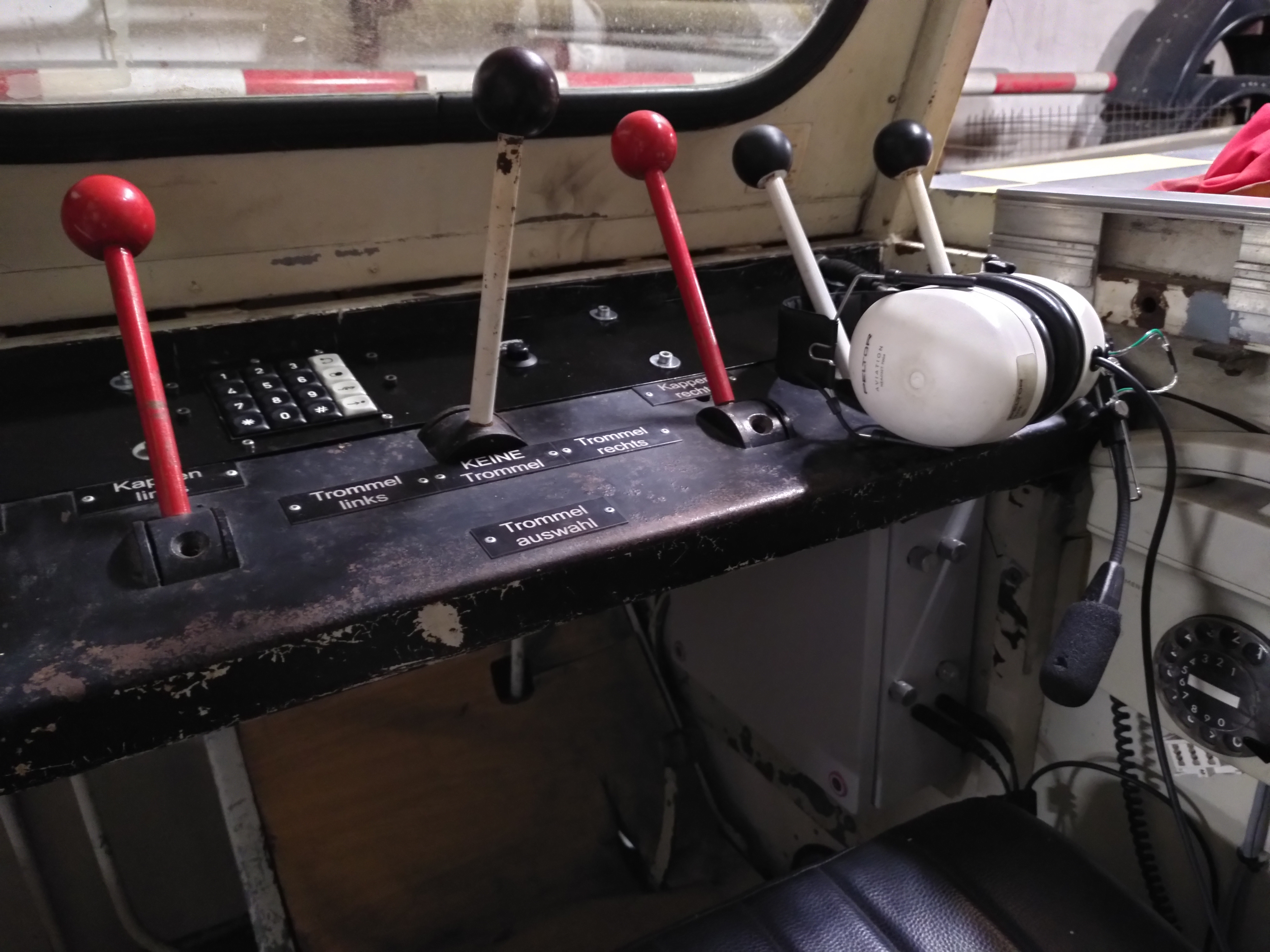
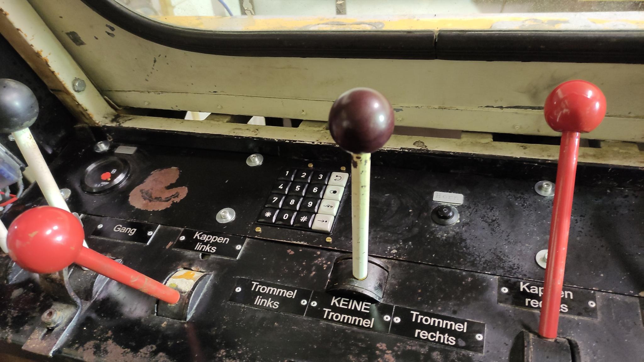
A view of the winch operators panel
A special phone for the winch operator on glider airfields is presented here. In contrast to most other projects on this site, it is a completely made up from in analog electronics.
It aims to provide more comfort to the the winch operator during launch communication using a headset compared to a conventional telephone receiver. Which needs to be held to the ear using the shoulder, as operation of a winch often needs both operators hands at certain stages of the towing sequence. Also when using gas driven winches, which at least for now is still the de-facto standard, it has the advantage that noise from the winch motor is muffled.
The disadvantage of a normal headset telephone is, however that other, partly important important sound sources can hardly be heard. So e.g. a aircraft radio receiver, PMR handheld radios, etc.
This gave rise to the idea of designing a headset phone, which could mix in other audio sources. For operational reasons, and being a hobbyist sport, it may take quite some time between two between two tows, so a possibility to listen to music from different sources would be nice.
However, it must be ensured that audio sources, which are not relevant during a launch sequence are switched off in time.
Hardware
The unit has a fully modular design, it consists of several modules, each only performing a well defined and limited amount of tasks. This way it is possible to introduce feature upgrades by simply swapping out individual modules and keeping the system as a whole mostly undisturbed.
Therefore an analog bus has been designed that takes care of signal mixing, mode switching and power supply. All other functions are implemented in the module boards themselves.
The bus consists of a 10 pin ribbon cable with the following signals:
| Pin | Pin | Signal | |
|---|---|---|---|
| +12V unregulated | 1 | 2 | Signal ground |
| Headset audio left | 3 | 4 | Headset audio right |
| Signal ground | 5 | 6 | +5V |
| Prio / Phone off hook | 7 | 8 | Power supply ground |
| Headset Microphone | 9 | 10 | Signal ground |

Intentionally ground lines for signal and power are kept separate for most of the boards. This reduces noise introduced by power supplies leaking into signal grounds in the asymmetric signaling within the unit. Both grounds are joined together on the main/power-in board.
All audio signals are being normalized by the modules to about 1 V rms, including the microphone, to again minimize received RF interference. The audio left/right signals are built as current loops and make a distributed mixing circuit with the main boards op-amps.
The line prio / phone off hook is active high (+5V relative to supply GND). If so, all the audio in cards feeding into the headset line should mute themselves if they are not considered priority-sources. The +5V are sourced from the phone board(s) and represents a wired-or that is intended to feed into NPN-bases via resistors and therefore be automatically zeroed if idle and no phone card is active.
For debugging and experimental extensions a 9 pin D-Sub connector carries all the busses Signals to the outside. I hope noone will ever try to connect a RS232 adapter, this might cause quite some damages on both ends. Looking at the pin mapping quickly, it seems rather safe, as most outputs of the bus are inputs on the RS232, but things might turn sour anyway.
Main board / headset i/o and power supply
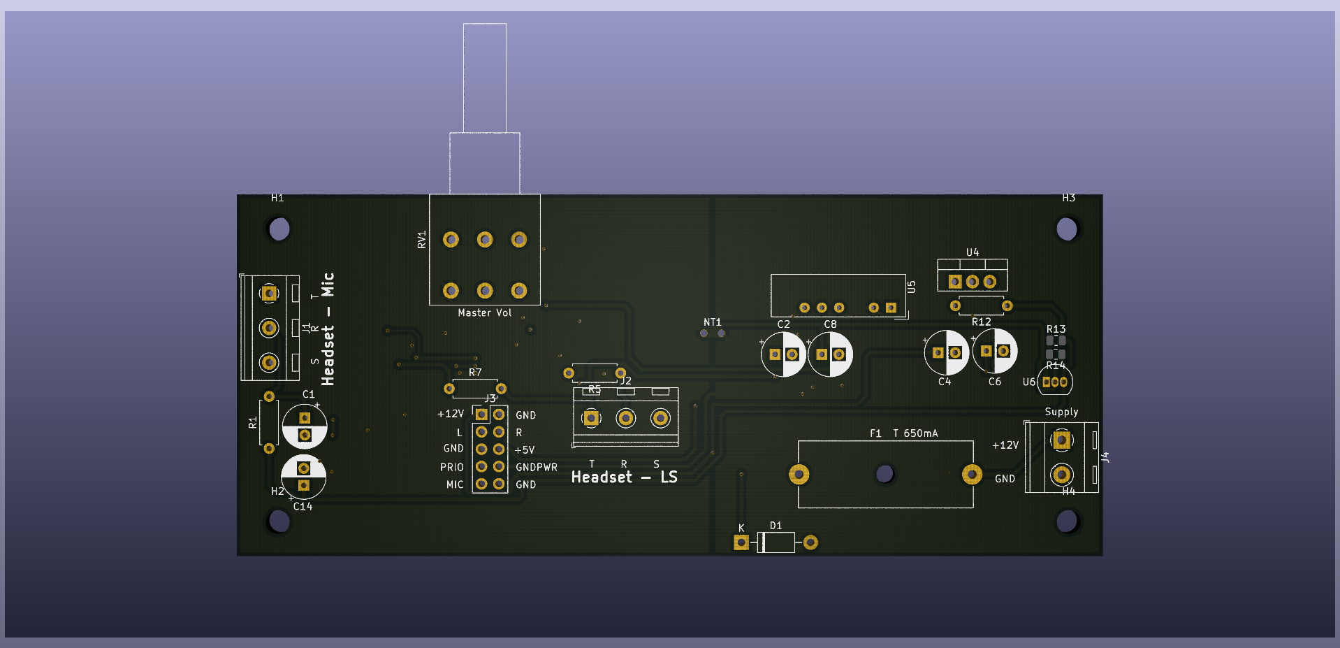
Headset and IO board KiCad render
This module serves two purposes: For one simply feeding the fused raw +12V, +5V for signaling into the bus.
On the other hand, it holds the headset drivers and the microphone interface
circuit.

The headset is biased using about +9V that are derived from the raw +12V using a shunt regulator in order to have good supply noise rejection and also tolerate quite a large input voltage swing.
 The microphone signal is amplified to about 1 V rms and is fed into the respective
bus line with 100 Ohm inline.
The microphone signal is amplified to about 1 V rms and is fed into the respective
bus line with 100 Ohm inline.
 Both left and right headset signals are summed up using an inverting op-amp
adder circuit using 10kΩ feedback. This could be used to set a default gain
for certain cards, but currently only 10kΩ output cards exist.
Both left and right headset signals are summed up using an inverting op-amp
adder circuit using 10kΩ feedback. This could be used to set a default gain
for certain cards, but currently only 10kΩ output cards exist.
 While bringing up the system, OpAmps U2B and U3B turned out to form a positive
feedback loop with R4/R8 (called R1 in the model) and their respecitve wiring capacitance,
which turned the whole amplifier into quite a nasty oscillator.
This was overlooked in first tests on breadboard as wiring capactance was not an issue
with short runs. But the bus wiring had a specified capacitance of 48pF/m, which lead to
phase shifts above 180 before the gain bandwith product ate all amplification and so
the whole thing went unstable.
While bringing up the system, OpAmps U2B and U3B turned out to form a positive
feedback loop with R4/R8 (called R1 in the model) and their respecitve wiring capacitance,
which turned the whole amplifier into quite a nasty oscillator.
This was overlooked in first tests on breadboard as wiring capactance was not an issue
with short runs. But the bus wiring had a specified capacitance of 48pF/m, which lead to
phase shifts above 180 before the gain bandwith product ate all amplification and so
the whole thing went unstable.

The capactors C15 and C16 in circuit (called C2 in model) over compensate the bus capacity
and therefore lead to a low pass behaviour with a cutoff-frequency of about 22 kHz.

The resulting left/right signals are passed through a dual wiper potentiometer for output volume control by the operator.
An NE5532 is used as a headset driver as it has a closed loop output impedance of about 300mΩ. This is more than sufficient for our use case, going down the rabbit hole of building a decent headset amplifier was not worth the effort.
Phone line interface

The old German POTS specifications result in voltages in excess of 100Vp (maybe even inverted, relative to GND). Also we are more than 700m (2300ft) away from the PBX, so we might expect some more earth potential difference as the winch system is heavily grounded on site. This leads to an undeniable risk of electric shocks when operating such a system on phone line potential.
All of this makes it a safer bet to go for a galvanically isolated phone line interface, which is achieved by isolated DC/DC converters and using audio transformers to get the signal from side to side.
The phone line is opened by the reed relay K1 when the phone is idle (prio line at 0V). At the same time, K2 shorts the received signal out, why this is needed will be obvious a little later.
When the phone is off-hook the prio line is fed +5V, K1 closes and K2 opens. From the PBX perspective, now the phone looks like transformer TR1 in series with a parallel circuit of 1kΩ (R4) and 100nF (C1).
Getting the received signal is rather straight forward, on the secondary side of TR1 the antiparallel diode circuit GG1 (german abbreviation for Gehörschutz-Gleichrichter which roughly translates to hearing protection rectifier) clamps the voltage to a reasonable level (~1 V pp). This is amplified by an op-amp if necessary and then fed via two 10kΩ to the left and right audio channels.
Coupling audio into the phone line is another, more tricky, thing as TR1 makes for a kind of circulator or T-Circuit which minimized the amplitude the sender hears its own voice. Building a modern circulator using op-amps was considered but just using old phone parts was quicker and hand the advantage of more likely being compliant enough for the circuit to work reliably.
In TR1 the microphone signal is coupled into kind of (not quite) center tap, so the transformer acts as an autotransformer towards the phone line and on the other hand the sent signal current cancels out in the secondary side.
Now it might be clean why one should mute the received signal, even when the phone line is decoupled from the system, the microphone signal is still coupled into TR1 and received sound is picked up from the transformer. As there is no line to drive in this situation, the circulator does not work either, making the audio feedback to the user worse. Therefore in idle mode, the received signal has to be muted.
In this module Murphy struck again, as the final PCBs tended to osciallate wildly when connected to our airfields PBX, likely caused by weird coupling through the audio transformers winding capacitance. This was fixed by putting two Y2 rated caps from the a/b lines to chassis ground, shoring the higher frequency AC path.
Its line circuit is most certainly compliant with the specifications our PBX expects to be kept for phones connected to it. German federal communication body was quite picky about the specs of the devices they put into citizens homes back when communications was still state owned. Therefore the components should be of quite a high quality, probably exceeding most commercial offerings today.
The most important components for the line impedance are: 1kΩ-Resistor R4, because this power resistor significantly influences the DC impedance and the current trough TR1. Also TR1 with its circulator features is sourced from said vintage phone.
A more recent model (FeTAp 745) from the 1970ies was used to source a dial keypad, which is connected via J4. This is, again built modularity in order to be swapped in case of a defect or an upgrade. (These old keypads only supported pulse dialing).
Audio input

Coupling in audio signals from other sources is a walk in the park compared with the phone interface.
This module is meant to be installed several times in the system. It serves several functions:
- coupling in stereo or mono signals
- interface listening aircraft/PMR/broadcast radios
- input can be populated to be line-in or alternatively dummy loudspeaker
- optional automatic muting upon picking up the phone
- all inputs galvanically isolated to avoid ground loops or RF interference
Both audio channels are exactly the same for most part, only J6 might bridge in left audio signal into right channel for mono usage.
The R1/R3-Network matches a given 4Ω/8Ω loudspeaker outputs (like from a car stereo) to the audio transformer TR1, if populated like drawn. For a plain line-in, one can jumper R5 and leave R3 out of circuit.
Both channels intentionally do not share a ground, again for not causing trouble when car stereos try to drive speakers in a full bridge configuration (H-Bridge).
On the secondary side of TR1 all signals are relative to the analog system ground.
The relay K1 takes care of muting the signal on demand, when Q1 gets switched by
PRIO_SW. The transformer drives trim potentiometer RV1 that can be used to
attenuate the signal, the op-amp U1 provides a gain of two. These set the maximum
volume.
The potentiometer RV3 on the other hand can be operated by the user to set a convenient volume. This drives the bus via the 10k resistors.
Measurements
To rate the circuit and get an understanding of how well the system operates, some measurements have been taken using an HP8903A Audio Analyzer.
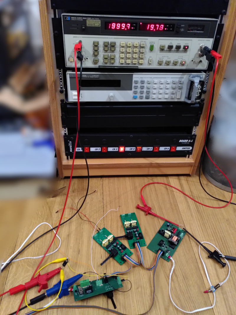
Test setup: from left to right: main board, 2x audio input, phone interface. Test equipment rack in the background
From mic to phone line
 The diagram above shows the system gain from microphone to phone line loaded with
a 600Ω termination resistor. The amplitude is not totally flat, but excursions of
-4.5dB are totally acceptable while giving some “color” to the sound.
The diagram above shows the system gain from microphone to phone line loaded with
a 600Ω termination resistor. The amplitude is not totally flat, but excursions of
-4.5dB are totally acceptable while giving some “color” to the sound.
One could try to fiddle with the feed impedance of TR1, risking instability of the output amplifier. The current constellation seems to be a good compromise between stability and performance.
From phone line to headset
 The plot above shows the amplitude gain from the phone line into the headset drivers.
It is rather flat from 150Hz to 9kHz, which is suitable for voice usage.
The plot above shows the amplitude gain from the phone line into the headset drivers.
It is rather flat from 150Hz to 9kHz, which is suitable for voice usage.
Line-in to headset
 Considering above frquency response, one can hardly miss the dampening of low frequency signals. Therefore this circuit is not always suitable for certain kinds of music, as the roll off point is somewhere around 150 Hz.
This still makes for a good voice-clearity but could leave some room for improvement in the music domain. But luckily when using a car stereo as a feed, it most likely comes with a tone control. Plus the 600Ω impedance of the analyzers source could by itself form a high pass with the input transformer.
Some dampening above 10 kHz could not hurt but this will be for a later revision of the boards or be bodged in at some point.
So we’ll see how it sounds in practice.
Mechanical assembly
All the mechanical assembly was done by another club member who spend countless hours in the airfields model airplane workshop. All the boards of the phone are built into a industrial wiring cabinet, which is situated on the right side of the winch operators legs.
Inside the cabinet all the modules are held together with long bolts and fixed to the walls using the potentiometers threads.
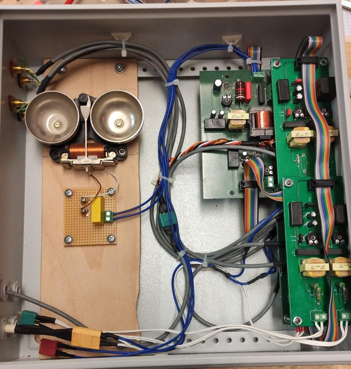
Internal assembly and wiring
The bell mechanism of the original phone was used for nostaly reasons and was simply screwed onto a heavy piece of oak plywood.
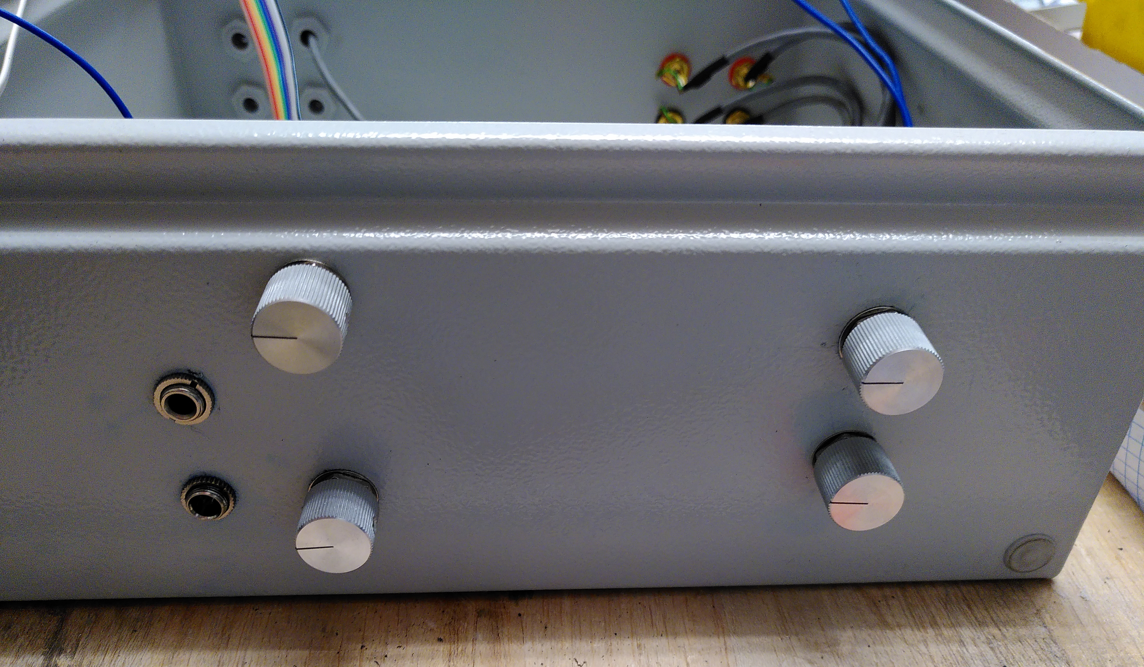
Volume control and headset jacks
The keypad comes from an old Siemens PBX phone which was similay to FeTAP 711 but already sported DTMF dialing. The electronics of this thing are a fascinating balst from the past in 80ies electonics. It took them three stacked boards of all through-hole components to pull this off. Its look matched the operator panel from the 70ies.
The keypad in its new home
The off-hook-switch is situated to the right of the operators console and is a heavy duty military grade marvel.
files
- phone_kicad.tgz Archive of all schematics and PCB designs of the project