On this page a modular system for the (halfway) neat construction of several Rasperry PI computers including mass storage and power supply.
The whole setup is powered using a semi-autonomous photovolatic DC power supply.
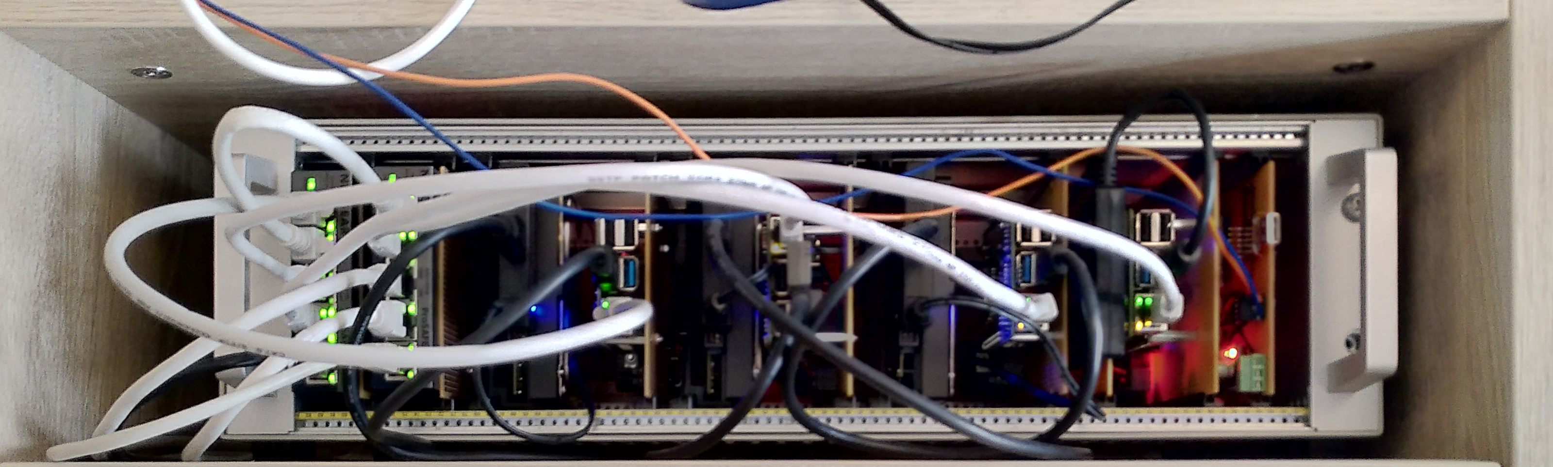
System in use
General
When running several Rasperry PIs or similar small modern single board computers it comes fast to cable tangle. Normally you need one power supply for each computer, one network cable, maybe also external USB hard disks. If you want to access the device locally (without SSH), you will need HDMI cables, a keyboard and possibly a mouse in addition only leads to more chaos.
If you now have several in operation, be it as a mini servers, testing environment for embedded systems or other purposes, the result is an almost almost impenetrable tangle of cables. Especially when a device is device is exchanged or rewired, this situation becomes even worse.
So now you want to achieve a mechanical organization that both creates order and facilitates maintenance.
Mechanics
The system is based on a standardized subrack system according to DIN IEC297-3. This allows the assembly of modules in the Eurocard format. Since the form factor of the Raspberry PI allows mounting on Eurocard and even some small network switches (e.g. the GS105 series from Netgear).
The individual cards are inserted into rails in the subrack and then connect by means of a 32-pin male multipoint connector according to DIN 41612 / IEC 60603-2 with a bus system which provides power supply and signal transport.
In this way, various components such as switches, computers and mass storage can be arranged and expanded relatively flexibly.
As 3.5" hard disks fit well into the housing but not between the the rails, support frames were designed and manufactured with the 3D printer.
Electronics
The bus
The bus is relatively simple in design, in this case female connectors with long pins, such as those used for wire-wrap construction, are screwed into the carrier.
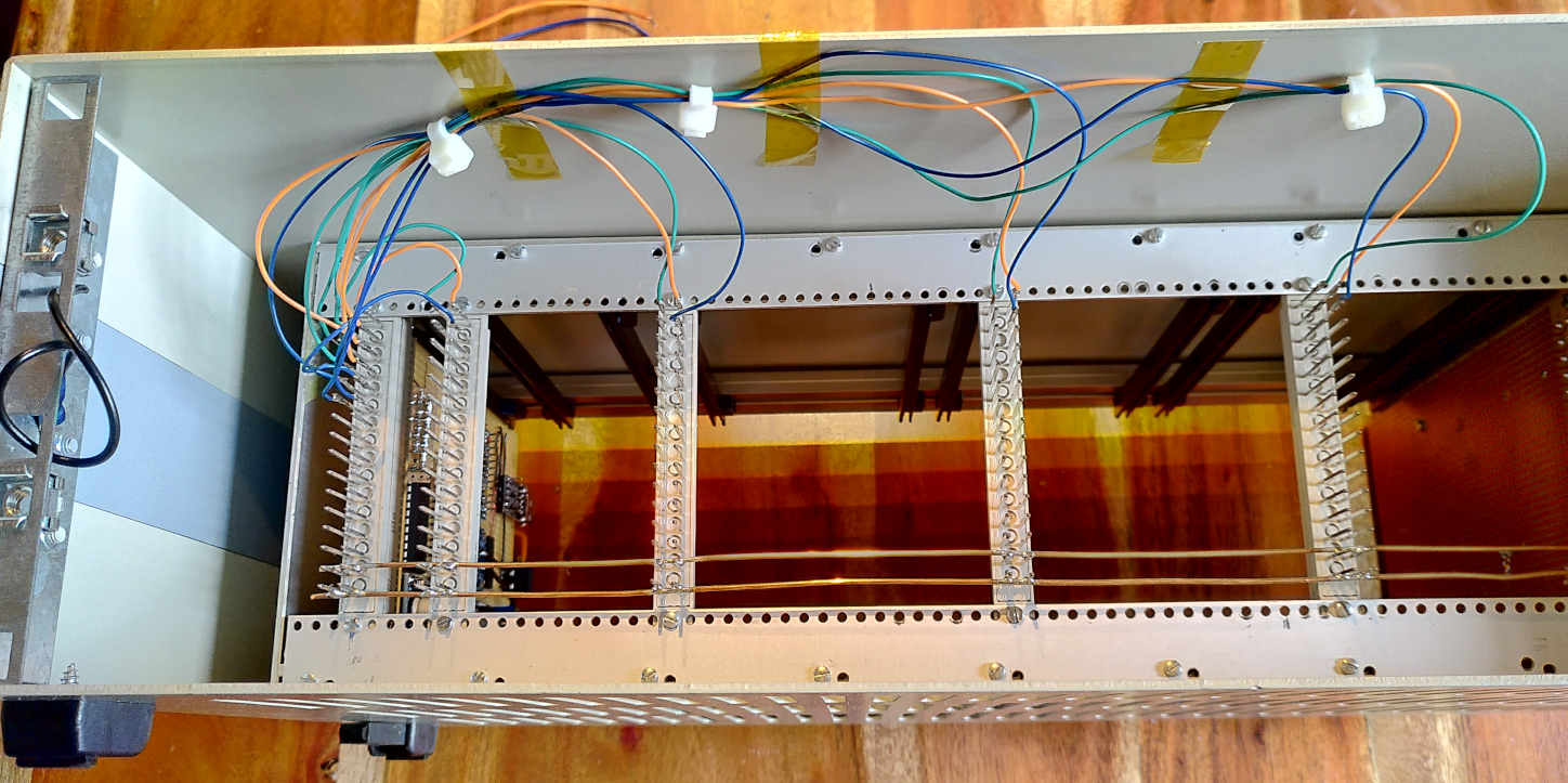
The Bus Wiring
The power supply is wired using 1,5mm^2 rigid wire from the from the house installation. It had beens staightened and laid between the individual contacts. This is simply soldered to the pins of the female connector. So the female connectors can be mounted with only four soldering joints and can be moved relatively easily over the entire width of the subrack.
There are three additional signal lines per computer, these are RXD/TXD for a serial console and RESET. Thus it is possible to operate the system quickly using software without mechanical intervention like pulling cards, plugging in keyboards and screens etc.
The modules
Control system
A new component of the system is the control module, it allows access to the serial consoles of the individual computers. By means of a USB-serial converter it is possible to communicate both with the microprocessor of the control module (based on the Arduino platform) and each and each individual computer.

The schematic of the controller board
The serial lines RXD and TXD are switched by multiplexers between the data sources. So the board is quasi transparent in the communication with the computers and influences the timing of the connection. This is in stark contrast to the buffering and forwarding of data by the microprocessor when using it as a kind of uart to uart bridge in software.
The entire subrack’s power can be supplied via the controller module, the input current and the supply voltage are measured via an INA260 IC.

Current and voltage sensor
Interesting is the way how the Arduino board is connected via the USB-Serial-Converter and can be accessed and programmed in the same way as it accessing the individual computers:

Wiring of the Controller
The RXD line of the Arduino is permanently connected to the USB-serial converter. So the processor can listen all the time and watch for a wakeup command, even during a connection with the single computer. The Arduino has a fixed baud rate of 115200 bps.
As a magic keyword, the sequence ‘+++’, known from the modem times, is used. Specifically, by sending three consecutive plus characters with a time interval of 10ms to 3s, the Arduino can be made to switch the multiplexer to the TXD of the Arduino. Thus it is accessible via the console.
If a command is given to switch the input (e.g. c0 for connecting
to the first computer), RXD and TXD are connected to the selected computer.
Firmware update on the controller is handled via the classic STK500 protocol also used on other Atmega based Arduino boards.
The low-active DTR line of the USB-serial converter triggers a reset of the processor. This starts a bootloader routine which then performs the update, if requested by the connected computer. If no upload is triggered, the controller starts the existing program.
But now the multiplexer circuit comes into play: Because the bootloader bootloader sets nearly all pins of the processor to high impedance. By means of the resistors R8..R11 the address lines the address lines of the multiplexers are pulled hight to logical 1, thus the Arduino is connected to the USB-serial converter when the arduino does not run any code.
However, the signal is not influenced by the 10k series resistors, which are used to protect devices in “hotplug mode”. The signal becomes so weak, that it cannot overpower internal pull-up resistors of the USB-to-serial converter. To fix this this, the classic HC14 buffer is applied, where two 74HC14 Schmitt Trigger inverters are connected in series to create a strong and non-inverted signal. Since the UART chip to the host works with 3.3V signals, the HC14 is operated accordingly already on 3V3.

Bus interface and multiplexer
Computer
The single computer modules are based on strip grid boards with male connectors.
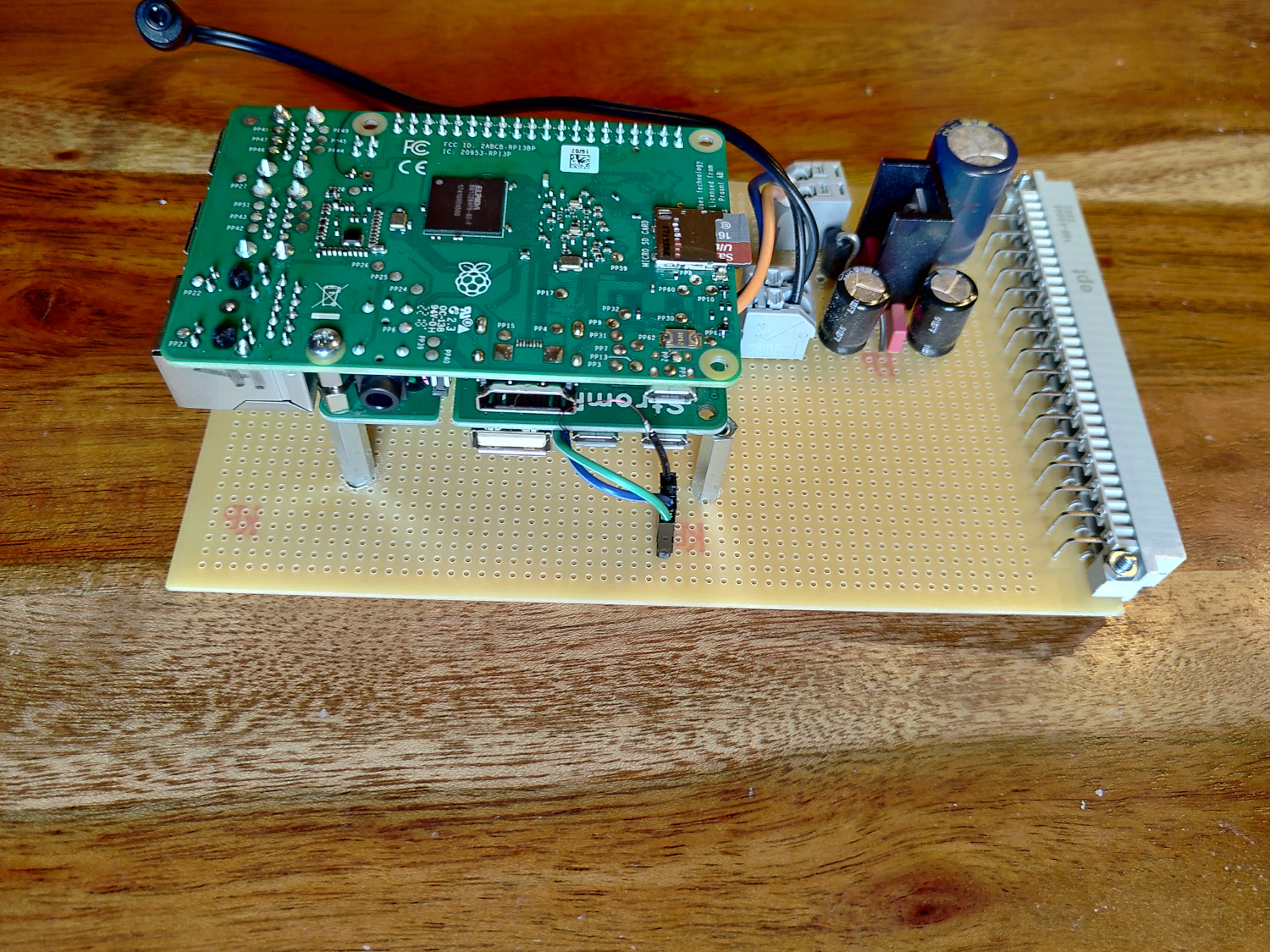
Single-board computer on plug-in card
The single board computers are fixed by M2.5 spacer bolts and are equipped with a piggyback module (HAT) with a DC/DC converter. This allows the 24V bus to power the computer.
The reset line, RXD and TXD of the computer are connected by means of jumpers and the strip grid card to the bus.
Additionally a switching regulator, based on the traditional LM2596 design, for external mass storage (mostly +12V) is available. This is connected to tension spring terminals, to which the hollow connectors for the mass storage USB adapter can be connected.
Mass storage
Here both classical rotating hard disks in special carriers can be used as well as SSD systems, simply mounted on breadboards.
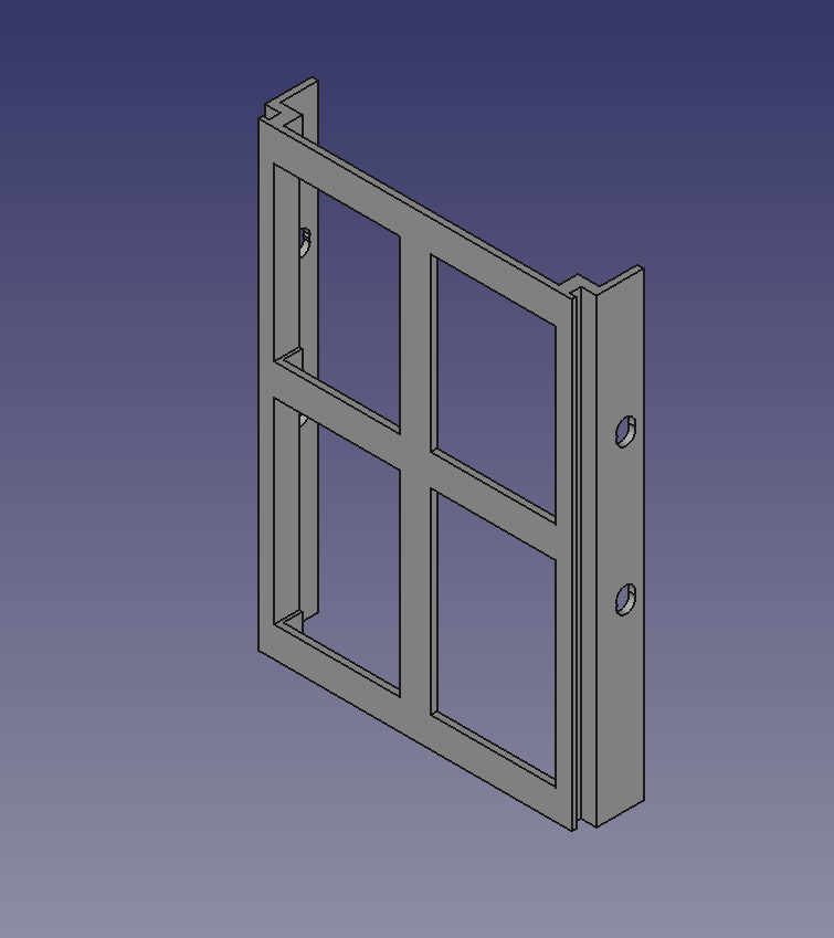
Hard disk carrier
switches
The Netgear GS105x series fits exactly on breadboards with male connectors. Even a LM2596 including circuitry fits on the board without any problems, so that modular network infrastructure can be built.
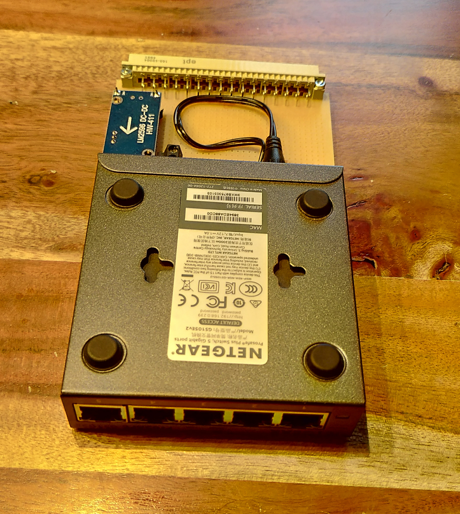
Switch mounted on breadboard
Software
The software of the controller board enables the control of the individual computers via the serial interface as well as via the external reset. Thus some problems can be diagnosed directly without pulling out the boards. Also the current power consumption can be queried.
The following commands are currently implemented:
| Command | Meaning | Example output |
|---|---|---|
c[0..3] |
Connect to computer x. | Will connect you to 0 |
r[0..3] |
Sends a reset signal to the computer | Sending reset to 0…done |
p |
Query current power consumption | Current: 1390.00 mA |
| Bus Voltage: 23923.75 mV | ||
| Power: 33260.00 mW |
Downloads
There are
- The HDD Holder
- the Arduino Code
- and the Schematic of the controller board for download